Shader Intermediates - Normal Mapping
An issue with the lighting examples seen in the previous chapter on lighting is that the entire surface of the object has a uniform appearance, making it appear flat.
Example - Stone wall
Square:
    World Position: { x: 0.000, y: 0.000, z: 0.000 }
    Lighting:
        Specular Reflectivity: 0.3
        Lobe Density: 5
Light:
World Position: { x: 4.000, y: 0.000, z: 4.000 }
Color: { r: 1.000, g: 1.000, b: 1.000 }
Intensity: 50In the above example of the stone wall, we've applied our naive approach to lighting the surface of the wall. The result is the appearance of a wall with detailed color, but looking very flat due to the simple form of lighting.
The wall shouldn't appear as flat since it has bumps, scratches, grooves, etc. These interact with light in different ways resulting in a surface that highlights the roughness and imperfections on it, giving it "depth".
A similar situation was discussed and solved in the chapter on color mapping, where the lack of color detail from vertex data was solved by passing color information using a texture.
The same concept of mapping can be used to add better lighting detail without increasing the complexity of the object. By changing the way the light interacts with the surface using a texture, the wall can be made to appear rough instead of smooth and flat.
Why store normals in a map?
If we look into the lighting chapter, we see that there are three main components being used to describe the object through its vertices.
- The vertex position.
- The vertex UV coordinates.
- The vertex normal.
Among these, the main component that affects the factor of lighting on an object is the vertex normal.
The reason for this is simple - the normal of a surface defines what direction the surface is facing, which is important for lighting.
Since the direction of the surface determines what amount of and how light will bounce and fall onto your eyes, this value can affect how a surface looks.

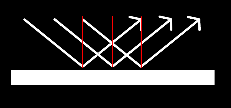
With a smooth surface, all points on the surface have their normals pointing in the same direction. This means that light falling on the surface bounces and reflects in the exact same manner across it, giving it a flat appearance, similar to the wall example seen above.

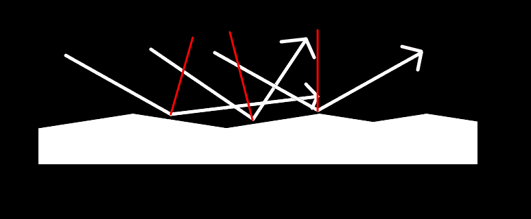
In contrast, a rough and bumpy surface has points with normals pointing towards different directions. This results in certain spots reflecting a lot more light towards the users view, while other spots reflect less, or completely reflect light away from the users view.
We can mimic the look of a rough surface by defining the normals of each point through the use of a texture, similar to how the color of each point of a surface was defined the same way in the color mappping chapter.
This provides the ability to generate lighting detail similar to if the object was modeled with its roughness described through polygons, but without the additional complexity and processing to deal with those polygons.
Just like with a diffuse map, a texture map used to describe the normals of an object is called a normal map, and the process of mapping normals of a fragment from a texture is called normal mapping.
Normal Maps
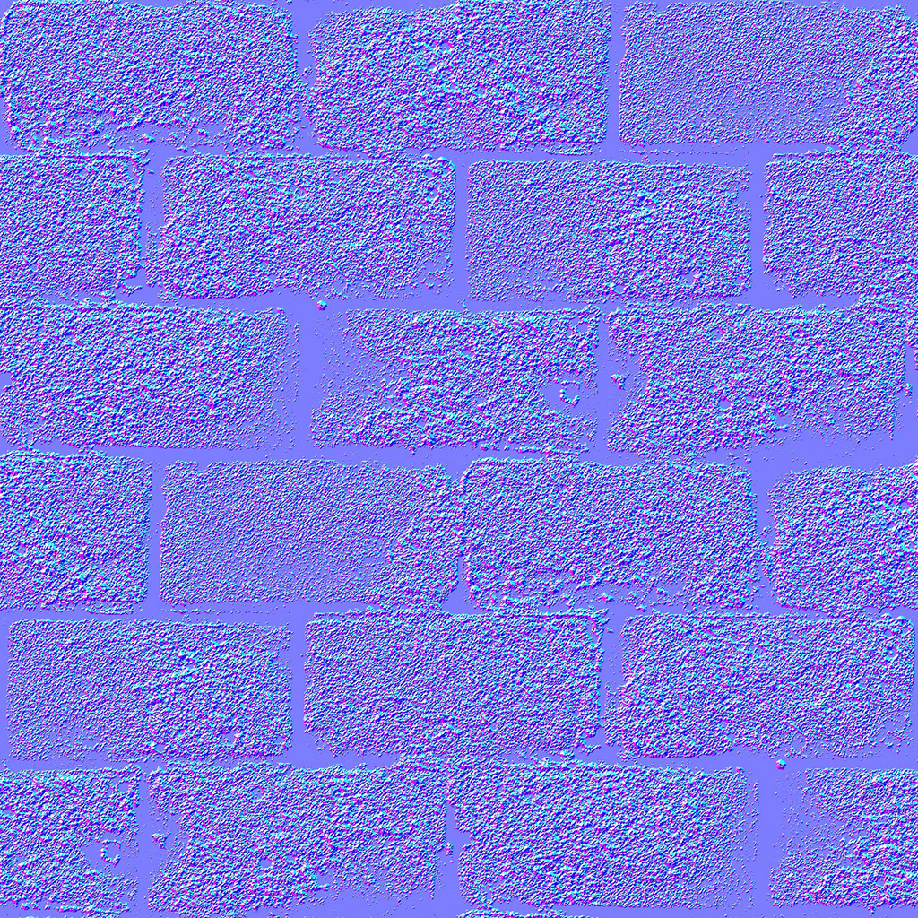
The texture maps that will be used to color and light the wall are:
The normal map is an image that contains the following information per pixel:
- The value of the normals are stored in the map as their unit vectors.
- The x-axis component of the normal is encoded as the red color of the pixel, with the color values 0 to 255 (0.0 - 1.0 in float) mapping into the range -1 to 1 on the x-axis.
- The y-axis component of the normal is encoded as the green color of the pixel, with the color values 0 to 255 (0.0 - 1.0 in float) mapping into the range -1 to 1 on the y-axis.
- The z-axis component of the normal is encoded as the blue color of the pixel, with the color values 128 to 255 (0.5 - 1.0 in float) mapping into the range 0 to 1 on the z-axis.
The reason why the z-axis is mapped only in the positive range is because any normal with a negative z-axis value is a direction that is pointing away from the view of the user, meaning that it would never be visible to the user anyways.
The values of the normals in the normal map are stored in a 2.5D space called "tangent-space".
Tangent-Space
Consider a sphere. A plane (a flat 2D surface) is considered "tangent" to a point on the sphere if the plane only touches the sphere at that point and not at any other neighbouring points.

Source
The plane shown here is the plane that is tangent to the point marked on the sphere. In other words, it is the tangent plane of the marked point on the sphere.
This plane is what is considered as XY-axis part of the tangent-space for that point of the sphere, with the Z-axis protruding outwards and away from the sphere (the direction of the normal of that point on the sphere).
In order to store the information of the normals of all points of that sphere, the values of the normals have to be recorded w.r.t the tangent-space of the point they belong to.
Calculating the lighting
Since the calculations we've seen in previous chapters are done in a space that is not the tangent-space, in order to use a normal map a transformation of values has to occur to ensure that the calculation occurs in the same "space" to be valid.
There are two potential options in order to fix calculations into a specific space:
- Keep other values as is, transform the normal map values from tangent-space into the other spaces, and perform the calculations in the other spaces.
- Keep the normal map values as is, transform all other values from other spaces into tangent-space, and perform the calculations in tangent-space.
In order to perform either of these, we'll need a certain matrix to perform the transformation. This matrix is called the Tangent-Bitangent-Normal matrix (or TBN matrix).
TBN Matrix
Just like with the model, view, and projection matrices, in order to transform values either into (or out of) tangent-space, a matrix called the TBN (Tangent Bi-Tangent Normal) matrix is required.
A TBN matrix for a vertex is calculated by generating a 3x3 matrix using the tangent, bi-tangent, and normal direction values of a vertex.
If we represent the tangent vector as T, bi-tangent vector as B, and normal vector as N, the TBN matrix would look like:
[AsciiMath Syntax:] TBN = [[T_x, B_x, N_x], [T_y, B_y, N_y], [T_z, B_z, N_z]]
Similar to how a model matrix can transform a point or direction from model-space into world-space, a TBN matrix can transform a point or direction from tangent-space into model-space.
Similarly, if the inverse of the TBN matrix is used instead, then the matrix can transform a point or direction from model-space into tangent-space. This is useful if you wish to keep calculations present in tangent-space.
Since the TBN matrix is calculated for each vertex, the matrix value for each fragment is interpolated from the matrix values for each vertex that forms the polygon that the fragment belongs to.
Let's look at an example where the calculation for lighting using the normal values in the normal map are done in view-space using the TBN matrix.
Example - Normal-mapped stone wall (in view-space)
Square:
    World Position: { x: 0.000, y: 0.000, z: 0.000 }
    Lighting:
        Specular Reflectivity: 0.3
        Lobe Density: 5
Light:
World Position: { x: 4.000, y: 0.000, z: 4.000 }
Color: { r: 1.000, g: 1.000, b: 1.000 }
Intensity: 50Vertex Shader Code:
1
2
3
4
5
6
7
8
9
10
11
12
13
14
15
16
17
18
19
20
21
22
23
24
25
26
27
28
29
30
31
32
33
attribute vec4 vertexPosition;
attribute vec2 vertexUv;
attribute vec3 vertexNormal;
attribute vec3 vertexTangent;
attribute vec3 vertexBiTangent;

uniform mat4 modelMatrix;
uniform mat4 viewMatrix;
uniform mat4 projectionMatrix;

varying highp vec2 uv;
varying highp mat3 tbnMatrix_viewSpace;
varying highp vec4 fragmentPosition_viewSpace;

void main() {
  highp vec4 vertexPosition_worldSpace = modelMatrix * vertexPosition;
  highp vec4 vertexPosition_viewSpace = viewMatrix * vertexPosition_worldSpace;
  gl_Position = projectionMatrix * vertexPosition_viewSpace;

  fragmentPosition_viewSpace = vertexPosition_viewSpace;
  uv = vertexUv;

  highp mat3 modelViewMatrix_3x3 = mat3(viewMatrix * modelMatrix);
  highp vec3 vertexTangent = normalize(vertexTangent);
  highp vec3 vertexBiTangent = normalize(vertexBiTangent);
  highp vec3 vertexNormal = normalize(vertexNormal);

  tbnMatrix_viewSpace = modelViewMatrix_3x3 * mat3(
    vertexTangent,
    vertexBiTangent,
    vertexNormal
  );
}
Fragment Shader Code:
1
2
3
4
5
6
7
8
9
10
11
12
13
14
15
16
17
18
19
20
21
22
23
24
25
26
27
28
29
30
31
32
33
34
35
36
37
38
39
40
41
42
varying highp vec2 uv;
varying highp mat3 tbnMatrix_viewSpace;
varying highp vec4 fragmentPosition_viewSpace;

uniform highp mat4 viewMatrix;
uniform highp vec4 lightPosition_worldSpace;

uniform highp vec3 lightColor;
uniform highp float lightIntensity;

uniform highp float specularLobeFactor;
uniform highp float specularReflectivity;

uniform sampler2D diffuseTextureSampler;
uniform sampler2D normalTextureSampler;

void main() {
  highp vec4 normalColor = texture2D(normalTextureSampler, uv);
  highp vec4 diffuseColor = texture2D(diffuseTextureSampler, uv);
  highp vec3 specularColor = vec3(diffuseColor.rgb);

  highp vec3 normal_viewSpace = tbnMatrix_viewSpace * normalize((normalColor.xyz * 2.0) - 1.0);

  highp vec4 lightPosition_viewSpace = viewMatrix * lightPosition_worldSpace;
  highp vec3 lightDirection_viewSpace = normalize((lightPosition_viewSpace - fragmentPosition_viewSpace).xyz);
  highp vec3 cameraPosition_viewSpace = vec3(0.0, 0.0, 0.0); // In view-space, the camera is in the center of the world, so it's position would be (0, 0, 0).
  highp vec3 viewDirection_viewSpace = normalize(fragmentPosition_viewSpace.xyz - cameraPosition_viewSpace);

  highp vec3 lightColorIntensity = lightColor * lightIntensity;
  highp float distanceFromLight = distance(fragmentPosition_viewSpace, lightPosition_viewSpace);

  highp float diffuseStrength = clamp(dot(normal_viewSpace, lightDirection_viewSpace), 0.0, 1.0);
  highp vec3 diffuseLight = (lightColorIntensity * diffuseStrength) / (distanceFromLight * distanceFromLight);

  highp vec3 lightReflection_viewSpace = reflect(lightDirection_viewSpace, normal_viewSpace);

  highp float specularStrength = clamp(dot(viewDirection_viewSpace, lightReflection_viewSpace), 0.0, 1.0);
  highp vec3 specularLight = (lightColorIntensity * pow(specularStrength, specularLobeFactor)) / (distanceFromLight * distanceFromLight);

  gl_FragColor.rgb = (diffuseColor.rgb * diffuseLight) + (specularColor.rgb * specularReflectivity * specularLight);
  gl_FragColor.a = diffuseColor.a;
}
The shaders are written similar to the final shader in the lighting chapter, but with all the main lighting calculation moved to the fragment shader. The reason for this is since we'd be grabbing the normal of the surface at the fragment level, the lighting can only be calculated in the fragment shader.
The first step is to calculate the TBN matrix which we need for transforming the normal values from tangent-space into view-space. This is done from line 22 onwards in the vertex shader.
The tangent, bi-tangent and normal values for each vertex in a model is known beforehand. These values are in model-space, and so need to be converted to view-space in order to calculate the TBN matrix in view-space.
The tangent, bi-tangent and normal values are first normalized (converted into a unit vector), and then a 3x3 matrix is constructed using them, as explained previously.
The resultant matrix is a TBN matrix that transforms vectors from tangent-space to model-space. Since we want to work in view-space instead, we multiply the model-view matrix against the TBN matrix to get a TBN matrix in view-space.
However, if you notice carefully, the TBN matrix is a 3x3 matrix, whereas a model-view matrix is a 4x4 matrix.
To transform the TBN matrix into view-space, the last column and last row of the model-view matrix can be removed in order to multiply it against the TBN matrix. This is fine because those fields don't contain any values that affect the calculation.
Alternatively, the TBN matrix can be converted into a 4x4 matrix, but this wouldn't provide much benefit as the resultant matrix would be used with vectors with three dimensions, not four.
The calculated TBN matrix in view-space is now passed to the fragment shader, along with certain other values that can only be calculated in the vertex shader (vertexPosition_viewSpace).
In the fragment shader, the normal value of the fragment is retrieved the normal map, similar to how the color value is retrieved from tge color map
Once the normal color value is retrieved, it needs to be converted into an actual normal vector (in tangent-space). Since we know what the range of the color values are supposed to represent, we can perform the conversion using a simple mathematical formula.
[AsciiMath Syntax:] "normal" = ("normalColor" * 2.0) - 1.0
Let's take a color value of whose RGB value is [AsciiMath Syntax:] "normalColor" = [128, 128, 128]. In OpenGL, the colors are represented in a range of 0 - 1 instead of 0 - 255, so the RGB value would actually be [AsciiMath Syntax:] "normalColor" = [0.5, 0.5, 0.5].
This color value is right in the middle of the color range, so it should represent a normal vector [AsciiMath Syntax:] "normal" = [0.0, 0.0, 0.0].
When we plug in the normal color value into our formula for calculating the normal, we get:
[AsciiMath Syntax:] "normal" = ([0.5, 0.5, 0.5] * 2.0) - 1.0 = [1.0, 1.0, 1.0] - 1.0 = [0.0, 0.0, 0.0]
Which matches perfectly with what we expect to get!
Just to further verify the formula, let's take a color value [AsciiMath Syntax:] "normalColor" = [64, 64, 192]. In OpenGL, this would be [AsciiMath Syntax:] "normalColor" = [0.25, 0.25, 0.75], which should represent a normal [AsciiMath Syntax:] "normal" = [-0.5, -0.5, 0.5].
Plugging this color value into the formula returns:
[AsciiMath Syntax:] "normal" = ([0.25, 0.25, 0.75] * 2.0) - 1.0 = [0.5, 0.5, 1.5] - 1.0 = [-0.5, -0.5, 0.5]
Which again equals to the expected normal vector.
Once the normal vector in tangent-space is calculated, it can now be transformed into view-space by multiplying the TBN matrix against it.
[AsciiMath Syntax:] "normal"_"viewSpace" = "TBN" times "normal"
Once this is calculated, the rest of the lighting calculations use this normal value to calculate the lighting on the fragment. This is similar to what was taught in the lighting chapter.
Now that we've seen what the calculation looks like in view-space, let's now look at how the calculation would appear in tangent-space.
Example - Normal-mapped stone wall (in tangent-space)
Square:
    World Position: { x: 0.000, y: 0.000, z: 0.000 }
    Lighting:
        Specular Reflectivity: 0.3
        Lobe Density: 5
Light:
World Position: { x: 4.000, y: 0.000, z: 4.000 }
Color: { r: 1.000, g: 1.000, b: 1.000 }
Intensity: 50Vertex Shader Code:
1
2
3
4
5
6
7
8
9
10
11
12
13
14
15
16
17
18
19
20
21
22
23
24
25
26
27
28
29
30
31
32
33
34
35
36
37
38
39
40
attribute vec4 vertexPosition;
attribute vec2 vertexUv;
attribute vec3 vertexNormal;
attribute vec3 vertexTangent;
attribute vec3 vertexBiTangent;

uniform mat4 modelMatrix;
uniform mat4 viewMatrix;
uniform mat4 projectionMatrix;

varying highp vec2 uv;
varying highp mat3 tbnMatrix_tangentSpace;
varying highp vec3 fragmentPosition_tangentSpace;

mat3 transpose(mat3 m) {
  return mat3(m[0][0], m[1][0], m[2][0],
              m[0][1], m[1][1], m[2][1],
              m[0][2], m[1][2], m[2][2]);
}

void main() {
  highp vec4 vertexPosition_worldSpace = modelMatrix * vertexPosition;
  highp vec4 vertexPosition_viewSpace = viewMatrix * vertexPosition_worldSpace;
  gl_Position = projectionMatrix * vertexPosition_viewSpace;

  uv = vertexUv;

  highp mat3 modelViewMatrix_3x3 = mat3(viewMatrix * modelMatrix);
  highp vec3 vertexTangent = normalize(vertexTangent);
  highp vec3 vertexBiTangent = normalize(vertexBiTangent);
  highp vec3 vertexNormal = normalize(vertexNormal);

  tbnMatrix_tangentSpace = transpose(modelViewMatrix_3x3 * mat3(
    vertexTangent,
    vertexBiTangent,
    vertexNormal
  ));

  fragmentPosition_tangentSpace = tbnMatrix_tangentSpace * (viewMatrix * vertexPosition_worldSpace).xyz;
}
Fragment Shader Code:
1
2
3
4
5
6
7
8
9
10
11
12
13
14
15
16
17
18
19
20
21
22
23
24
25
26
27
28
29
30
31
32
33
34
35
36
37
38
39
40
41
42
43
44
varying highp vec2 uv;

varying highp mat3 tbnMatrix_tangentSpace;
varying highp vec3 fragmentPosition_tangentSpace;

uniform highp mat4 modelMatrix;
uniform highp mat4 viewMatrix;
uniform highp vec4 lightPosition_worldSpace;

uniform highp vec3 lightColor;
uniform highp float lightIntensity;
uniform highp float specularReflectivity;
uniform highp float specularLobeFactor;

uniform sampler2D diffuseTextureSampler;
uniform sampler2D normalTextureSampler;

void main() {
  highp vec4 normalColor = texture2D(normalTextureSampler, uv);
  highp vec4 diffuseColor = texture2D(diffuseTextureSampler, uv);
  highp vec3 specularColor = vec3(diffuseColor.rgb);

  highp vec4 lightPosition_viewSpace = viewMatrix * lightPosition_worldSpace;
  highp vec3 lightPosition_tangentSpace = tbnMatrix_tangentSpace * lightPosition_viewSpace.xyz;
  highp vec3 lightDirection_tangentSpace = normalize(lightPosition_tangentSpace - fragmentPosition_tangentSpace);

  highp vec3 normal_tangentSpace = normalize((normalColor.xyz * 2.0) - 1.0);

  highp vec3 lightColorIntensity = lightColor * lightIntensity;
  highp float distanceFromLight = distance(fragmentPosition_tangentSpace, lightPosition_tangentSpace);

  highp float diffuseStrength = clamp(dot(normal_tangentSpace, lightDirection_tangentSpace), 0.0, 1.0);
  highp vec3 diffuseLight = (lightColorIntensity * diffuseStrength) / (distanceFromLight * distanceFromLight);

  highp vec3 cameraPosition_viewSpace = vec3(0.0, 0.0, 0.0); // In view-space, the camera is in the center of the world, so it's position would be (0, 0, 0).
  highp vec3 viewDirection_tangentSpace = normalize(fragmentPosition_tangentSpace.xyz - cameraPosition_viewSpace);
  highp vec3 lightReflection_tangentSpace = reflect(lightDirection_tangentSpace, normal_tangentSpace);

  highp float specularStrength = clamp(dot(viewDirection_tangentSpace, lightReflection_tangentSpace), 0.0, 1.0);
  highp vec3 specularLight = (lightColorIntensity * pow(specularStrength, specularLobeFactor)) / (distanceFromLight * distanceFromLight);

  gl_FragColor.rgb = (diffuseColor.rgb * diffuseLight) + (specularColor.rgb * specularReflectivity * specularLight);
  gl_FragColor.a = diffuseColor.a;
}
Since the TBN matrix we previously had transformed vectors from tangent-space to view-space, in order to transform values the other way we need to calculate the transpose of the TBN matrix we previously calculated. This is done in line 33 of the vertex shader.
Once the new TBN matrix is calculated, we now transform all the values we were previously using in view-space into tangent space. In the vertex shader, we transform the vertex position into tangent-space, and in the fragment shader we transform the light position into tangent-space.
Once in the fragment shader, we grab the normal vector from the normal map as we did in the previous example. Since the lighting calculations are being done in tangent-space, only the conversion from the color value to the vector value is required.
Now that all the variables we require for calculating lighting are in tangent-space, we can perform the lighting calculations in the exact same way as in the previous example. The resultant lighting value will be the same!
Summary
- Similar to color mapping, normal mapping can be used to map normals to fragments inside a polygon to add more detail to a surface.
- Normal maps add the appearance of roughness or small bumps on the surface of objects.
- The normals of each point are stored in an image in "tangent-space" with the X, Y, and Z coordinates represented using RGB color values.
- The color values representing the normals for each fragment are retrieved from the texture and then converted into normal vectors, which are then used to perform lighting calculations.
- Check out this guide by Matt Rittman on how to generate a normal map in Photoshop. You should find other references for generating normal maps online.

