
Shader Intermediates - Lighting
While adding textures to color your objects helps to add more detail, simulating the lighting of the environment on the object adds further detail and makes it appear in place with the rest of the world.
There are three components of light reflection that come into effect when simulating light falling on an object:
- The diffuse component
- The ambient component
- The specular component
Let's look at each component, and how they effect the look of the object when simulating lighting. We'll only work with a single point light, which has light rays going from a single point in every direction, but the same principles apply to other kinds of lights, as well as multiple sources of light.
But before that, let's look at how the cube appears with no lighting for reference.
The Diffuse Component
The first component is the diffuse component and is the primary reflection component that lights up objects.
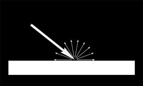
When a ray of light hits an object, due to the roughness and texture of the object, this light spreads out and reflects in multiple directions.
However, not all of the light is reflected. Certain colors that are part of the light are absorbed by the object, with the rest being reflected. The colors that are reflected by the object are the ones that we see, which means these are the colors which we see as being the color of that object.
For example, when white light falls on an apple, we see that the apple is red. This is because white light is made up of multiple colors in a spectrum mixed together.
The colors that are not red are absorbed by the surface of the apple, and the red components of light that remain are reflected. This results in us seeing the apple as being red.
The light that shows us this color is what we consider as the diffuse component of the light reflection of the apple.
The diffuse component is dependent on four factors:
- The color of the light - If the light is red and the object is blue, since these two colors are completely separate in the color spectrum, all the light is absorbed by the object and nothing is reflected, making the object appear black (or having no color).
- The intensity of the light - The brighter the source of light is, more light will hit an object, making it appear brighter (unless the example in the first point occurs).
- The distance of the light source from the object - The further away a source of light is from an object, the less intense the light will be when it hits the object. This is due to theinverse-square law, which states that the intensity of the light is inversely proportional to the square of the distance between the light source and the object.
- The angle at which the light hits the object - This we'll explain below.
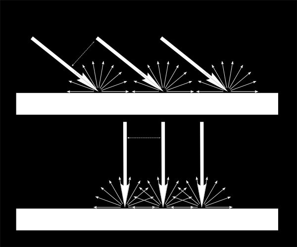
If the light hits the surface of the object at an angle, the light gets spread out over a wide surface.
However, if the light hits the surface at an angle that's closer to perpendicular to the surface of the obejct, then a lot more light gets concentrated across a smaller surface, making the surface appear brighter.
This can be done through an experiment as well. Grab your phone and turn on the flashlight (or else grab a torch) and shine it perpendicularly away by a certain distance on a rough surface and note down the brightness.
Next, shine it from approximately the same distance at an acute angle to the surface, with the light source being the same distance away as in the first test.
The brightness of the surface should decrease when the light is shining at an angle compared to when it was perpendicularly, and is why the angle of the light compared to the surface of the object matters.
These four factors combined together affect how the diffuse reflection will finally appear.
Since the diffuse component is what shows the color of an object, the color map used to color an object is also called a diffuse map, since it provides the color that the diffuse reflection is supposed to show.
Example - Cube with diffused reflection
Cube:
    World Position: { x: 4.000, y: 4.000, z: 4.000 }
Light:
World Position: { x: 4.000, y: 4.000, z: 4.000 }
Color: { r: 0.300, g: 0.300, b: 0.300 }
Intensity: 50How it works
We now know that diffuse light is the light that shows the color of the surface of an object, and it's brighter when the incident light is closer to being perpendicular to the surface, its color falls within the color spectrum of the object, has a high intensity, and is close to the object.
The first thing required is the normal of the surface being lighted. A normal can be considered as a direction that is perpendicular to a surface. So if there was a surface that was across the XZ-plane, then it's normal would be any direction along the Y-axis.
Since we can only tell the GPU information about each vertex, the normal of the plane is set as the normal of each vertex forming that plane.
This way when the entire plane is being drawn, since all vertices have the same normal, the entire plane will also be interpolated to have that normal.
The second thing required is the direction of the light. Since the position of the light and objects in the world are known, and the light is a point light, the direction would be from the light source to the object itself.
In order to determine the brightness of a point on the surface of the object, the angle between the normal of the surface and the direction of light must be compared.
The mathematics
If the direction of the light is perpendicular to the surface, then the angle between the direction of light and the normal of the surface will equal 0 degrees, resulting in the brightness at that point should be brightest.
Conversely, if the direction of the light is parallel to the surface, then the angle between the direction of light and the normal of the surface will be 90 degrees, which results in no light hitting the surface and its brighness being zero.
Consider brightness as a factor from 0 to 1, where at 1, the brightness is at its highest possible value, and at 0, it is at it's lowest possible value.
So a mathematical operation is required which, when given an angle of 0 degrees provides a result of 1, and when given an angle of 0 degrees provides a result of 0.
The best operation for this is the trignometric function [AsciiMath Syntax:] cos(theta), where [AsciiMath Syntax:] theta is the angle between the two directions.
Do note that if the angle between the normal and the light is greater than 90 and upto 180, the result of this operation goes upto -1. So the result of the operation needs to be clamped to 0 to prevent the diffuse factor from being negative, since you can't have a negative amount of light.
In the GPU, we'll be representing the directions of the surface normal and light direction in the form of vectors. So a mathematical operation is required between two vectors, which can provide us with the [AsciiMath Syntax:] cos(theta) result of the angle between them. This operation is the dot product.
Let us take two vectors [AsciiMath Syntax:] vec v_1 and [AsciiMath Syntax:] vec v_2. The dot product of these two vectors would be [AsciiMath Syntax:] vec v_1 cdot vec v_2 = norm(vec v_1) norm(vec v_2) cos(theta), where [AsciiMath Syntax:] norm(vec v_1) and [AsciiMath Syntax:] norm(vec v_2) represent the magnitute of [AsciiMath Syntax:] vec v_1 and [AsciiMath Syntax:] vec v_2 respectively.
The magnitude of a vector can be considered as a certain quantity that is required to move a point from one place to another. The magnitude combined with the direction of the vector forms the vector itself.
If we move around parts of this equation, we can represent this as equation as [AsciiMath Syntax:] (vec v_1) / norm(vec v_1) cdot (vec v_2) / norm(vec v_2) = cos(theta), where [AsciiMath Syntax:] (vec v) / norm(vec v) is considered the unit vector of the vector (represented as [AsciiMath Syntax:] hat(v)), because the magnitude of the vector is removed from the vector itself, leaving it as a single unit of itself that purely represents its direction.
This results in the final equation being [AsciiMath Syntax:] hat(v_1) cdot hat(v_2) = cos(theta), where [AsciiMath Syntax:] hat(v_1) and [AsciiMath Syntax:] hat(v_2) represent the unit vectors of the vectors [AsciiMath Syntax:] vec v_1 and [AsciiMath Syntax:] vec v_2. So we can determine the [AsciiMath Syntax:] cos(theta) of two vectors by finding the dot product of their unit vectors. This can be done easily, because there are built-in functions that let us calculate the unit vector of a given vector.
Including the other factors that affect the diffuse reflection, the final equation is:
[AsciiMath Syntax:] "diffuseLight" = ((hat "lightDirection" cdot hat "surfaceNormal") times "lightColor" times "lightIntensity") / "distance" ^ 2
The factors are combined through multiplication and division and not addition and subtraction, because addition would mean that these factors pile up on each other. However, these factors mix with each other to determine the final factor of the diffuse reflection, which is done through multiplcation and division.
Let us look at the code to see how this equation is implemented.
Vertex Shader Code:
1
2
3
4
5
6
7
8
9
10
11
12
13
14
15
16
17
18
19
20
21
22
23
24
25
26
27
28
29
30
31
attribute vec4 vertexPosition;
attribute vec2 vertexUv;
attribute vec3 vertexNormal;

uniform mat4 modelMatrix;
uniform mat4 viewMatrix;
uniform mat4 projectionMatrix;

uniform vec4 lightPosition_worldSpace;
uniform vec3 lightColor;
uniform float lightIntensity;

varying highp vec2 uv;
varying highp vec3 diffuseLight;

void main() {
  highp vec4 vertexPosition_worldSpace = modelMatrix * vertexPosition;
  highp vec4 vertexPosition_viewSpace = viewMatrix * vertexPosition_worldSpace;
  gl_Position = projectionMatrix * vertexPosition_viewSpace;

  uv = vertexUv;

  highp vec3 lightColorIntensity = lightColor * lightIntensity;
  highp float distanceFromLight = distance(vertexPosition_worldSpace, lightPosition_worldSpace);
  highp vec3 normal_viewSpace = normalize((viewMatrix * modelMatrix * vec4(vertexNormal, 0.0)).xyz);
  highp vec4 lightPosition_viewSpace = viewMatrix * lightPosition_worldSpace;
  highp vec3 lightDirection_viewSpace = normalize((lightPosition_viewSpace - vertexPosition_viewSpace).xyz);

  highp float diffuseStrength = clamp(dot(normal_viewSpace, lightDirection_viewSpace), 0.0, 1.0);
  diffuseLight = (lightColorIntensity * diffuseStrength) / (distanceFromLight * distanceFromLight);
}
Fragment Shader Code:
1
2
3
4
5
6
7
8
9
10
11
varying highp vec2 uv;
varying highp vec3 diffuseLight;

uniform sampler2D colorTextureSampler;

void main() {
  highp vec4 surfaceColor = texture2D(colorTextureSampler, uv);

  gl_FragColor.rgb = surfaceColor.rgb * diffuseLight;
  gl_FragColor.a = surfaceColor.a;
}
In the vertex shader, the lines 17-21 are the standard operations we've seen in previous chapters, so they can be mostly ignored.
The important things to note from them is that the results of the position of the vertex in the world-space and view-space (see the Vertex Shader Basics if you need to recollect) are saved in certain variables which will be required later.
After those lines, we first calculate the combined product of the light color and intensity, which is a simple multiplication. This result is stored in a vec3 named lightColorIntensity, since it stores the intensity of each color (R, G, and B) of the light.
The distance between the light source and object is very simple. Since the positions of both are already stored in vectors, the distance between them can be calculated through a built-in function available in shading languages. In GLSL, this function is distance.
Alternatively, the two vectors can be subtracted into another vector, and the magnitude of that resultant vector would give us the distance between the two points. The magnitude of a vector can be calculated in GLSL using the built-in function length.
The direction of the normal of the vertex is required to be known respective to the camera, which is why the calculation of the normal in view-space (multiplying the model and view matrices) is performed and stored in normal_viweSpace. This is similarly done for the direction of the light and stored in the lightDirection_viweSpace.
A point of note is that the direction of the light is stored as the direction from the object to the light source. This allows our calculations to be accurate, since if the light is falling perpendicular to the surface, then the direction of the light is the same as the normal of the vertex. This results in the dot product of the two directions equaling 1, which is what we require.
If the direction of the light was stored as the direction from the light source to the object, then the resulting dot product of the direction of the light and the vertex normal would be -1, because the two vectors are pointing in the opposite direction.
The vectors calculate for the vertex normal and light direction in view-space are converted into a unit vector, which is used to calculate the diffuse factor by the angle of the light and the normal of the surface. In GLSL, the built-in function for this calculation is normalize.
The reason for normalizing vectors is so that we remove the influence of magnitudes of vectors from calculations. A normalized vector only provides information regarding its direction, but not the magnitude of the direction. Since certain calculations we perform only require the directions of vectors, those vectors are normalized.
The diffuse strength (strength of the diffuse reflection from the angle of the light and the surface) is calculated by finding the dot product of normal_viewSpace and lightDirection_viewSpace (done through the built-in function dot in GLSL). This is clamped between 0 and 1 to prevent a negative diffuse strength.
The final diffuse reflection factor of the object is calculated by multiplying the diffuse strength calculated in the previous step with the product of the light color and intensity.
This result is then divided by the square of the distance between the light and the object, which is required due to the inverse-square law.
This final diffuse factor is then passed to the fragment shader, allowing the value to be interpolated per fragment. The diffuse factor is multiplied with the surface color of the fragment to determine the final color of that fragment.
Do note that the alpha value of the fragment color is not multiplied, since the transparency of an object won't change based upon the light falling on it.
The Ambient Component
The ambient component is the second component of lighting reflection, and is generally a much more subtle form of reflection. Ambient reflection is not from direct interaction with the light source, but interaction with the rest of the environment.
The rays of light from the light source hit other objects as well, and the light reflected from these other objects in the environment bounce around and eventually hit the primary object as well.
This light that comes indirectly through light bouncing of other objects form the ambient component of lighting of an object, causing the object to always have a minimum amount of brightness, either over the entire object or over a certain area.
Since this the minimum brightness of an object caused due to the environment, the diffuse lighting component adds on top of the ambient component.
Example - Cube with ambient and diffuse reflections
Cube:
    World Position: { x: 4.000, y: 4.000, z: 4.000 }
    Lighting:
        Ambient Factor: 0.1
Light:
World Position: { x: 4.000, y: 4.000, z: 4.000 }
Color: { r: 0.300, g: 0.300, b: 0.300 }
Intensity: 50Fragment Shader Code:
1
2
3
4
5
6
7
8
9
10
11
12
13
varying highp vec2 uv;
varying highp vec3 diffuseLight;

uniform highp float ambientFactor;
uniform sampler2D colorTextureSampler;

void main() {
  highp vec4 surfaceColor = texture2D(colorTextureSampler, uv);
  highp vec4 ambientColor = vec4(surfaceColor);

  gl_FragColor.rgb = (ambientColor.rgb * ambientFactor) + (surfaceColor.rgb * diffuseLight);
  gl_FragColor.a = surfaceColor.a;
}
How it works
Since the ambient component of lighting is just a minimum brightness of the object due to the environment, the ambient factor doesn't need any calculation, so the vertex shader requires no modification.
The ambient color is the color that the object produces when hit with ambient light. This is the same as the diffuse color of an object in most cases, which is why we're setting the ambient color the same as the diffuse color. However, you could set this to a different color to create interesting effects.
The ambient factor of the environment is directly passed to the fragment shader, which is then multiplied with the ambient color of the fragment to introduce the minimum brightness.
This is then added along with the diffusion component of lighting, since the ambient lighting is the base brightness of the object, and the diffusion component is an addition on top of it to further increase the brightness of surfaces being hit by the light.
The Specular Component
The specular component is the final component of lighting reflection and is what gives objects a "shine".
Specular reflection is similar to reflection by a mirror. When a ray of light hits the surface, depending on the smoothness of the surface, this light may be completely reflected, like as if the surface were a mirror.
If the reflected light is seen by the viewer, it would look like all, or a part of the light was reflected by the object, giving the impression the object has a shiny surface. This is specular reflection.
Just like how with diffuse reflection the brightness is dependent on the angle of the light and the surface, with specular reflection the brightness is dependent on the direction of the reflected light and the direction of the camera.
Other than this factor, specular reflection is also dependent on all the other factors that diffuse reflection is.
Example - Cube with all lighting components
Cube:
    World Position: { x: 4.000, y: 4.000, z: 4.000 }
    Lighting:
        Ambient Factor: 0.1
        Specular Reflectivity: 0.5
        Lobe Density: 5
Light:
World Position: { x: 4.000, y: 4.000, z: 4.000 }
Color: { r: 0.300, g: 0.300, b: 0.300 }
Intensity: 50How it works
We can reuse the principles we've learnt from diffuse reflection. We know that a factor of diffuse lighting is the angle of the reflected light with the direction of the camera.
The mathematics
If the direction of the camera is known, as well as the direction of the reflected light, by applying the dot operation we've learnt, we can calculate the the [AsciiMath Syntax:] cos(theta) angle between them, which gives us the strength of the specular reflection.
The same [AsciiMath Syntax:] cos(theta) operation is required here since the same principle applies - the closer the light reflection and the camera are in the same direction, the brighter the specular reflection will appear to be.
Another point to note is when calculating the dot product of these two vectors, they must be in the relatively same direction.
What is meant by this is, if the direction of the camera is taken as the direction from the camera to the object, then the direction of the reflected light has to also be taken from the point the light is travelling towards to the object.
If this condition is not satisfied, the two directions will appear to be completely opposite to each other, resulting in their dot product being in the opposite sign than they should be (negative when it should be positive and vice-versa).
Another alternate solution to this issue is to multiply the result of the dot product with -1 to get the correct result. Either solution can be applied.
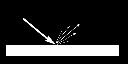
According to the law of reflection, the angle at which a ray of light hits a surface (angle of incidence) is equal to the angle at which the light reflects off the surface (angle of reflection).
Since the normal of a surface is always perpendicular to the surface, this angle of incidence and angle of reflection are against the normal of the surface.
An image showing this law is below:
We've already know the direction of the light to the object when calculating diffuse reflection. Using the normal of the surface, the direction of the reflected light can be calculated.
Once the dot product of the direction of the reflected light and direction of the camera is calculated, it is combined with other factors resulting in the final equation:
[AsciiMath Syntax:] "specularLight" = ((hat "lightDirection" cdot hat "cameraDirection")^"Lobe Density" times "lightColor" times "lightIntensity") / "distance" ^ 2
The lobe density defines how concentrated the specular reflection is over a surface. A lower value means that the light is reflecting over a larger surface area, and a higher value means that the light is reflecting over a smaller surface area.
Let us look at the code to see how this equation is implemented.
Vertex Shader Code:
1
2
3
4
5
6
7
8
9
10
11
12
13
14
15
16
17
18
19
20
21
22
23
24
25
26
27
28
29
30
31
32
33
34
35
36
37
38
39
attribute vec4 vertexPosition;
attribute vec2 vertexUv;
attribute vec3 vertexNormal;

uniform mat4 modelMatrix;
uniform mat4 viewMatrix;
uniform mat4 projectionMatrix;

uniform vec4 lightPosition_worldSpace;
uniform vec3 lightColor;
uniform float lightIntensity;
uniform float specularLobeFactor;

varying highp vec2 uv;
varying highp vec3 diffuseLight;
varying highp vec3 specularLight;

void main() {
  highp vec4 vertexPosition_worldSpace = modelMatrix * vertexPosition;
  highp vec4 vertexPosition_viewSpace = viewMatrix * vertexPosition_worldSpace;
  gl_Position = projectionMatrix * vertexPosition_viewSpace;

  uv = vertexUv;

  highp vec3 lightColorIntensity = lightColor * lightIntensity;
  highp float distanceFromLight = distance(vertexPosition_worldSpace, lightPosition_worldSpace);
  highp vec3 normal_viewSpace = normalize((viewMatrix * modelMatrix * vec4(vertexNormal, 0.0)).xyz);
  highp vec4 lightPosition_viewSpace = viewMatrix * lightPosition_worldSpace;
  highp vec3 lightDirection_viewSpace = normalize((lightPosition_viewSpace - vertexPosition_viewSpace).xyz);

  highp float diffuseStrength = clamp(dot(normal_viewSpace, lightDirection_viewSpace), 0.0, 1.0);
  diffuseLight = (lightColorIntensity * diffuseStrength) / (distanceFromLight * distanceFromLight);

  highp vec3 viewDirection_viewSpace = normalize(vertexPosition_viewSpace.xyz - vec3(0.0, 0.0, 0.0));
  highp vec3 lightReflection_viewSpace = reflect(lightDirection_viewSpace, normal_viewSpace);

  highp float specularStrength = clamp(dot(viewDirection_viewSpace, lightReflection_viewSpace), 0.0, 1.0);
  specularLight = (lightColorIntensity * pow(specularStrength, specularLobeFactor)) / (distanceFromLight * distanceFromLight);
}
Fragment Shader Code:
1
2
3
4
5
6
7
8
9
10
11
12
13
14
15
16
varying highp vec2 uv;
varying highp vec3 diffuseLight;
varying highp vec3 specularLight;

uniform highp float ambientFactor;
uniform highp float specularReflectivity;
uniform sampler2D colorTextureSampler;

void main() {
  highp vec4 surfaceColor = texture2D(colorTextureSampler, uv);
  highp vec4 ambientColor = vec4(surfaceColor);
  highp vec4 specularColor = vec4(1.0);

  gl_FragColor.rgb = (ambientColor.rgb * ambientFactor) + (surfaceColor.rgb * diffuseLight) + (specularColor.rgb * specularReflectivity * specularLight);
  gl_FragColor.a = surfaceColor.a;
}
In the vertex shader, the new code is from line 33. First the direction of the camera is calculated. Since the object is in view, the direction of the camera would be everywhere in view of the camera.
A direction vector is calculated by subtracting the vector that represents the source point from the vector that represents the point the direction is pointing towards.
In the case for calculating the direction of the camera, it is calculated by subtracting the position of the camera from the direction of the object.
In view-space, the camera is always at the center of the world, since in view-space, everything is positioned relative to the camera. This is why the position of the camera is taken as vec3(0.0, 0.0, 0.0).
This direction is normalized so that the resultant vector calculated is the unit vector that represents the just direction of the camera, with no magnitude.
The light direction in view-space is known, along with the direction of the normal of the surface. Using a built-in function, the reflection of the direction of light w.r.t to the normal can be calculated. In GLSL, this function is reflect.
The result of the reflection calculation is not normalized since the direction of the incident light is already a unit vector, so it's resultant reflection will also be a unit vector.
A point of note is that with reflect in GLSL, the light direction still points away from the object, not towards it.
Imagine the normal of the surface as a mirror. When calculating the reflection of the light direction relative to the normal, the reflection would appear on the other side of the normal, but the direction won't change.
This is shown in the illustration below:


Since the direction calculated for the camera is from the object to the camera, the calculation of the dot product of the camera direction and the light direction will still be accurate, since they are both pointing away from the object.
This calculation is done in the next step to determine the strength of the specular reflection. Similar to the same calculation for the diffusion strength, this result is also clamped to between 0 and 1 to prevent a negative strength result.
The final specular reflection factor is then calculated in the same way as the diffusion factor - multiply the specular strength with the light color and intensity, and divide it by the square of the distance of the light source from the object.
Since the specular factor is also dependent on the specular lobe density of the light, it is increased to the power of the lobe density. So the more dense the light specular lobe is, the specular factor of the light on the surface increases exponentially.
The result is then passed to the fragment shader, allowing it to be interpolated per fragment.
The specular reflectivity is the value that determines how reflective or smooth the surface of the object is.
The surfaces of objects aren't always perfectly smooth, but have very small bumps in them. When light falls on an object, only a portion of the light would be reflected by these bumps perfectly towards the camera. The rest of the light would be reflected in other directions and not contribute to the specular lighting component.
If we set the specular reflectivity of the surface to 1.0, it means that all of the light is reflected by the surface of the object towards the camera, making the surface of the object perfectly smooth.
However, if we set the specular reflectivity to 0.5, only 50% of the light is reflected towards the camera by the surface of the object, with the rest being reflected in other directions.
In our case, we've set the specular reflectivity to 0.5, meaning that the cube only reflects 50% of the light falling on it.
The color of specular lighting is also dependent on the specular color that the surface emits during specular reflection, as the surface can absorb part of the light, and reflect the rest of it, resulting in it having a different color.
The specular color value is generally set to the color of the object, but we set the specular color value to [AsciiMath Syntax:] (1.0, 1.0, 1.0) as we want all the light falling on the surface to be reflected without any parts being absorbed.
The specular factor is multiplied against the specular reflectivity and the specular color of the fragment, and then added to the other lighting reflection components to set the final color value of the fragment.
Per-vertex vs Per-fragment lighting
All lighting factors we calculated was done on the vertex shader, which is then passed to the fragment shader, allowing the GPU to interpolate the factor for each fragment. This is doing lighting calculations "per-vertex".
The reason that this is done on the vertex shader and not the fragment shader is to reduce the number of calculations, similar to why the MVP matrix is passed directly instead of the multiplication being done on the GPU.
There will always be considerably more fragments that a fragment shader would have to process than vertices that a vertex shader would have to process.
This means that any calculations done on a fragment shader will be done much more in comparison to a calculation done on the vertex shader.
To save on computation time, if there is a calculation on the fragment shader can be performed on the vertex shader and then interpolated for each fragment, it is recommended to perform that calculation on the vertex shader.
This optimization reduces the number of overall computations performed and relies on the GPU interpolating values correctly.
However, this may not always produce accurate results. Since the GPU has to interpolate the lighting values of the fragments inside the polygon based on the values returned for each vertex, it is possible for inaccuracies to be present.
Let's illustrate with an example to show how per-vertex lighting can produce incorrect results compared to per-fragment lighting.
Square:
    World Position: { x: 0.000, y: 0.000, z: 0.000 }
Light:
World Position: { x: 0.500, y: 0.200, z: 3.000 }
Color: { r: 1.000, g: 1.000, b: 1.000 }
Intensity: 2.25Here we have a light source (represented as the red triangle) present near the center of a wall, shining towards it. The light is focused towards the center of the wall, making the inside of the wall brighter than the corners and edges.
This is rendered by performing the lighting calculations on the fragment instead of on the vertex, meaning that the light is calculated on a "per-fragment" basis.
Calculating the lighting on the fragment shader results in a much more accurate result since the light values of the fragments inside the polygon aren't interpolated from the vertex.
Only the locations of the fragments, and their normals are interpolated from there, which has no issues since interpolating the position of a fragment based on the position of its vertices is simple for GPUs to do.
Now lets look at how the lighting looks if we perform the lighting calculation for each vertex instead and let the GPU interpolate those lighting values for the fragments inside the polygons.
Square:
    World Position: { x: 0.000, y: 0.000, z: 0.000 }
Light:
World Position: { x: 0.500, y: 0.200, z: 3.000 }
Color: { r: 1.000, g: 1.000, b: 1.000 }
Intensity: 2.25The results when performing lighting calculations per-vertex are much more inaccurate compared to if the calculations are performed per-fragment.
The reason for this is simple: the amount of light falling on the corners of the wall is lower than the amount of light falling at the center of the wall.
This means that when calculating the lighting values at the vertices, since the amount of light is lower due to the further distance from the light source, the results will be low.
Now the GPU only has information on the lighting values for each vertex. It has no information regarding the light source or how these values are calculated.
As a result, when it needs to interpolate the lighting values at the center of the wall, it can only assume that the amount of light falling on the center of the screen is somewhere in between the amount of light falling on each vertex.
The resolution (amount of detail) in per-vertex lighting is dependent on the number of vertices being drawn. The more vertices being processed, the more data the GPU has available to interpolate the values for the rest of the fragments.
However, the resolution for per-fragment lighting is equal to the number of fragments being drawn. Since we perform the lighting calculation for each fragment, we know that the final lighting calculation will be accurate for that fragment.
The only thing really required for per-fragment lighting is interpolating the position of a fragment in a polygon. This can always be easily interpolated by the GPU since the position of a fragment can always be interpolated using the positions of the vertices and where the fragment is present relative to those vertices.
Now let's look at our cube example, but with per-fragment lighting calculations.
Cube:
    World Position: { x: 4.000, y: 4.000, z: 4.000 }
    Lighting:
        Ambient Factor: 0.1
        Specular Reflectivity: 0.5
        Lobe Density: 5
Light:
World Position: { x: 4.000, y: 4.000, z: 4.000 }
Color: { r: 0.300, g: 0.300, b: 0.300 }
Intensity: 50Vertex Shader Code:
1
2
3
4
5
6
7
8
9
10
11
12
13
14
15
16
17
18
19
20
21
22
attribute vec4 vertexPosition;
attribute vec2 vertexUv;
attribute vec3 vertexNormal;

uniform mat4 modelMatrix;
uniform mat4 viewMatrix;
uniform mat4 projectionMatrix;

varying highp vec2 uv;
varying highp vec4 fragmentPosition_viewSpace;
varying highp vec3 fragmentNormal_viewSpace;

void main() {
  highp vec4 vertexPosition_worldSpace = modelMatrix * vertexPosition;
  highp vec4 vertexPosition_viewSpace = viewMatrix * vertexPosition_worldSpace;

  gl_Position = projectionMatrix * vertexPosition_viewSpace;

  fragmentPosition_viewSpace = vertexPosition_viewSpace;
  fragmentNormal_viewSpace = normalize((viewMatrix * modelMatrix * vec4(vertexNormal, 0.0)).xyz);
  uv = vertexUv;
}
Fragment Shader Code:
1
2
3
4
5
6
7
8
9
10
11
12
13
14
15
16
17
18
19
20
21
22
23
24
25
26
27
28
29
30
31
32
33
34
35
36
37
38
39
40
varying highp vec2 uv;
varying highp vec4 fragmentPosition_viewSpace;
varying highp vec3 fragmentNormal_viewSpace;

uniform highp mat4 viewMatrix;
uniform highp vec4 lightPosition_worldSpace;

uniform highp vec3 lightColor;
uniform highp float lightIntensity;

uniform highp float ambientFactor;

uniform highp float specularLobeFactor;
uniform highp float specularReflectivity;

uniform sampler2D colorTextureSampler;

void main() {
  highp vec4 surfaceColor = texture2D(colorTextureSampler, uv);
  highp vec4 ambientColor = vec4(surfaceColor);
  highp vec4 specularColor = vec4(1.0);

  highp vec4 lightPosition_viewSpace = viewMatrix * lightPosition_worldSpace;
  highp vec3 lightDirection_viewSpace = normalize((lightPosition_viewSpace - fragmentPosition_viewSpace).xyz);
  highp vec3 viewDirection_viewSpace = normalize(fragmentPosition_viewSpace.xyz - vec3(0.0, 0.0, 0.0));

  highp vec3 lightColorIntensity = lightColor * lightIntensity;
  highp float distanceFromLight = distance(fragmentPosition_viewSpace, lightPosition_viewSpace);

  highp float diffuseStrength = clamp(dot(fragmentNormal_viewSpace, lightDirection_viewSpace), 0.0, 1.0);
  highp vec3 diffuseLight =  (lightColorIntensity * diffuseStrength) / (distanceFromLight * distanceFromLight);

  highp vec3 lightReflection_viewSpace = reflect(lightDirection_viewSpace, fragmentNormal_viewSpace);

  highp float specularStrength = clamp(dot(viewDirection_viewSpace, lightReflection_viewSpace), 0.0, 1.0);
  highp vec3 specularLight = (lightColorIntensity * pow(specularStrength, specularLobeFactor)) / (distanceFromLight * distanceFromLight);

  gl_FragColor.rgb = (ambientColor.rgb * ambientFactor) + (surfaceColor.rgb * diffuseLight) + (specularColor.rgb * specularReflectivity * specularLight);
  gl_FragColor.a = surfaceColor.a;
}
You can see that the lighting in this example is different compared to the previous cube example, and shows how per-vertex lighting can produce incorrect results if not used correctly.
In our code, we've moved all lighting calculations onto the fragment shader. The vertex shader only provides the fragment shader with values that the GPU should always be able to correctly interpolate for each fragment.
The fragment shader can then calculate the final lighting values for each fragment using the interpolated results.
The values being passed to the fragment shader from the vertex shader are:
vertexPosition_viewSpaceThe position of the vertex in view-space. This is interpolated into the position of the fragment in view-space.Since the vertex position describes where a vertex is located, and the position of each vertex determine where a polygon is located, the position of a fragment can be interpolated through the position of each vertex of the polygon it is present in.vertexNormal_viewSpaceThe position of the vertex in world-space. This is interpolated into the normal of the fragment in view-space.Since the vertex normal describes which direction a vertex is facing, and the normals of each vertex determine which direction a polygon faces, the normal of a fragment can be interpolated through the normals of each vertex of the polygon it is present in.
In future examples with lighting, we'll be performing the lighting calculations per-fragment instead of per-vertex for more accuracy.
Additional Notes
This process can also be called shading, since we are "shading" an object based on how light falls on it. Certain topics taught later also fall under the process of shading since the contribute to the way an object is "shaded".
A point of note is that for specular lighting we provided a value to control how much of the light is reflected towards the camera (the specular reflectivity).
For diffuse lighting, the roughness of the surface should also be considered when calculating how much of the light is diffused by the object, since a rougher surface would diffuse more light than a smooth one.
However, the roughness of the surface can be multiplied against the color of the surface and stored as part of the color map itself, resulting in a map called a "diffuse map".
In later chapters, we'll be using a diffuse map instead of a simple color map to provide diffuse color information.
Summary
- Lighting helps to make an object seem more in place with the world
- There are three reflection components when lighting an object:
- Diffuse Component - The component that shows us the color and look of the object. Brightness depends on at what angle the light hits the surface.
- Ambient Component - The component that is resultant from the light reflected by the rest of the environment onto the object. Results in the object always having a minimum amount of brightness.
- Specular Component - The component that is resultant from the light reflected by the object towards the camera. Results in the object looking like it has a reflective surface.
- When the main three lighting components are combined, they simulate realistic lighting of an object in a basic form.